This page describes the experimental facilities and capabilities that are developed and used by our research group at Penn State.
Aircraft Noise Measurement System
Our group has developed a system for conducted outdoor noise measurements of aircraft. The aircraft noise measurement system currently supports arrays of up to 36 measurement microphones, which can be distributed over a wide area to capture aircraft ground noise footprints. Battery-powered field-deployable data acquisition systems record the measured microphone data at 24 bit resolution at sampling rates of up to 131 kHz. Acoustic data is synchronized between data acquisitions systems, and with aircraft state data, using GPS time synchronization. 
The aircraft noise measurement system being deployed.
Acoustic data are primarily collected using 1/2″ IEC Class I measurement microphones in custom-made inverted ground-plane microphone installations based on the SAE ARP 4055 guidelines. A survey grade GPS system is used to precisely locate each microphone position. Elevated microphone installations are also available, and can be configured in accordance with FAR Part 36 noise certification standards. Ground based meteorological sensors are available to measure atmospheric conditions during noise measurements. 
Typical aircraft noise measurement microphone installations.
The aircraft noise measurement system has been used to conduct measurements of several aircraft operated by industry partners at remote test sites. This system has also been used to collect noise measurements of numerous UAS at a nearby test site described in the following section.
Acoustics Research UAS
Several Uncrewed Aerial System (UAS) aircraft have been developed to support aeroacoustics research in collaboration with the PSU UAS Research Laboratory (PURL). Extensive outdoor noise measurements have been conducted using a custom-built reconfigurable multirotor UAS, shown below in a hexacopter configuration. 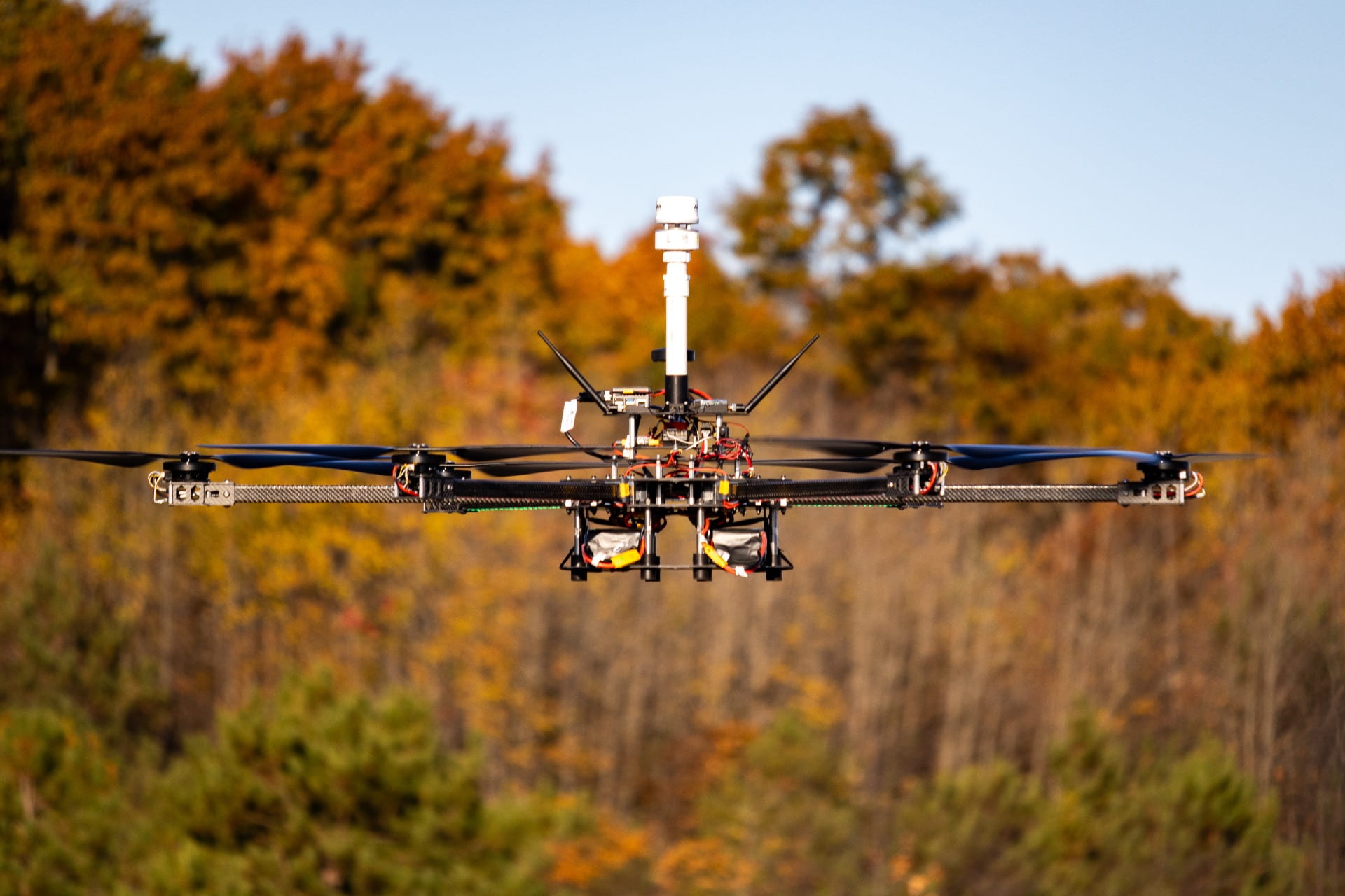
Reconfigurable multirotor UAS in a hexacopter configuration in hovering flight.
The UAS can be configured with a varied number of rotor arms with single or dual coaxial rotor mounts, supporting a range of common multicopter configurations. In the hexacopter configuration shown above, the vehicle has a diameter of approximately 2.3 m from rotor tip to rotor tip with a mass of 16 kg, including batteries and research instrumentation. Onboard instrumentation records the vehicle’s attitude, attitude rate, and acceleration using the on board flight control system, vehicle position using a centimeter-accurate real-time kinematic differential GPS (RTK-DGPS) system, and rotor RPM and shaft position using instrumented motors. Recently, an air data system has been installed on the vehicle to enable measurements of airspeed/wind speed and direction, outside air temperature, static pressure, and humidity. All measured data are synchronized to GPS time so that they can be correlated to data collected using the previously described aircraft noise measurement system. Acoustic data flights are typically conducted autonomously, with the aircraft precisely flying a pre-programmed mission plan, with a safety pilot monitoring the operation and prepared to take manual control. An airband radio is available to monitor and communicate with local air traffic. Outdoor UAS noise measurements are primarily conducted at a test site located at the Mid-State Regional Airport in Phillipsburg, PA. The airport is surrounded by Black Moshannon State Park and Moshannon State Forest and features very low ambient noise levels. 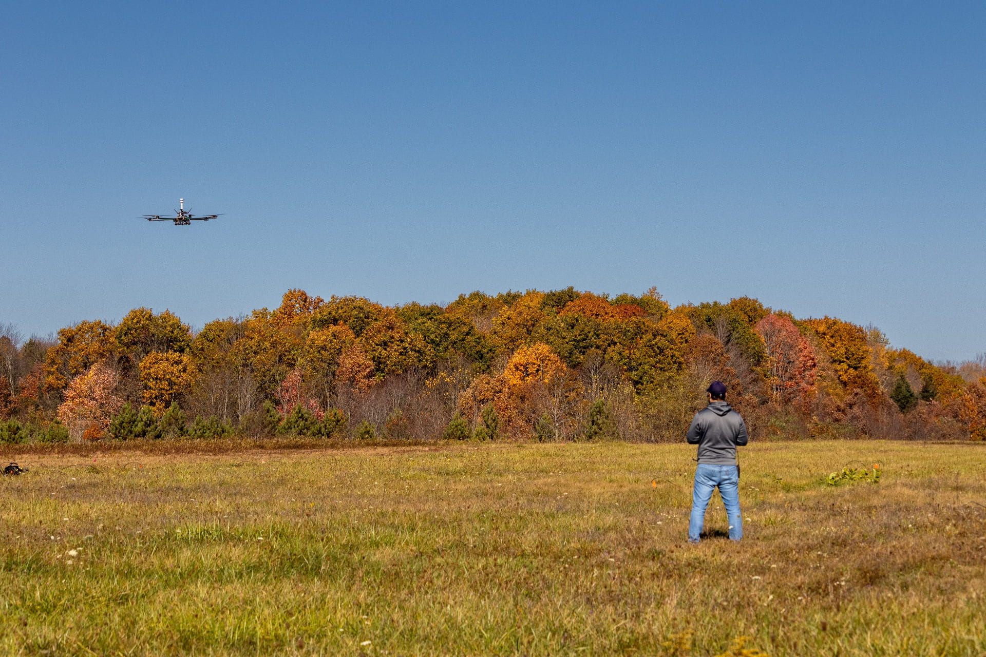
Vehicle designer, pilot, and PhD student Vitor T. Valente operating the UAS at Mid-State Regional Airport.
Open Jet Flow-through Anechoic Chamber
The Open Jet Flow-through Anechoic Chamber is a 5.0 x 6.0 x 2.8 m room covered with fiberglass wedges, with an approximate cut-off frequency of 250 Hz. An open jet wind tunnel is incorporated in the facility for experiments conducted with a forward flight stream. A mixed flow design, developed for minimal noise, provides the inlet flow. This flow is delivered to an axial flow muffler and acoustically treated duct work leading to the anechoic chamber inlet. An acoustically treated collector and duct work leads to an exhaust fan on the exit side of the system. This design results in an open jet, inside the chamber that is close to ambient pressure. Different nozzles may be attached to the inlet to the chamber to adjust the size of the open jet and the flow velocity. Although the facility was originally developed for aeroacoustic experiments using small scale helium-air jets—a capability that is still in place—recent upgrades have also enabled rotor aeroacoustics experiments to be conducted. Following upgrades to add a return circuit to the wind tunnel, the flow speed has been increased to 20 m/s for the 0.6 x 0.6 m open jet typically used in rotor aeroacoustics experiments. 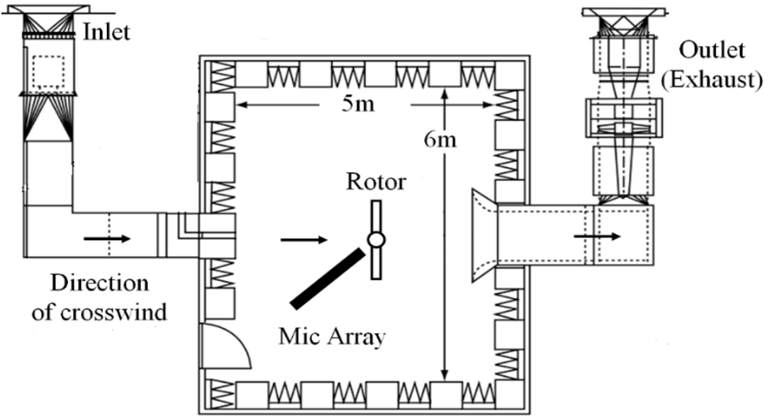
Top-view schematic of the Open Jet Flow-through Anechoic Chamber.
Multirotor Test Rig
A multirotor test rig has been installed in the Open Jet Flow-through Anechoic Chamber to support aerodynamic and acoustic experiments involving multirotor aircraft systems. The test rig is highly reconfigurable, allowing two rotors to be placed in the flow stream with varied positions and orientations relative to the flow and one another. Pitch-adjustable rotor hubs are available for two, three, four, and six bladed rigid rotor systems. Custom rotor blades can be manufactured at Penn State using a sterolithography (SLA) 3D printing process. Six degree of freedom force and moment measurements can be made independently for each rotor to measure aerodynamic performance. Rotor RPM and shaft angle are also measured independently for each rotor. A rotor phase control system has also been developed, enabling the two rotors to be phased locked together without any mechanical connections between the rotors. Acoustic measurements are typically made using a linear array of 1/4″ or 1/2″ measurement microphones mounted on a rotary actuator so that the array can be traversed around the rotor system. Microphone stands and aerodynamic “bullet nose” windscreens are available for measurements at other locations in the chamber, include inside of the open jet flow steam. A small acoustic phased array is also available for acoustic source localization. In addition, a hotwire traverse system is available for in-flow turbulence measurements. 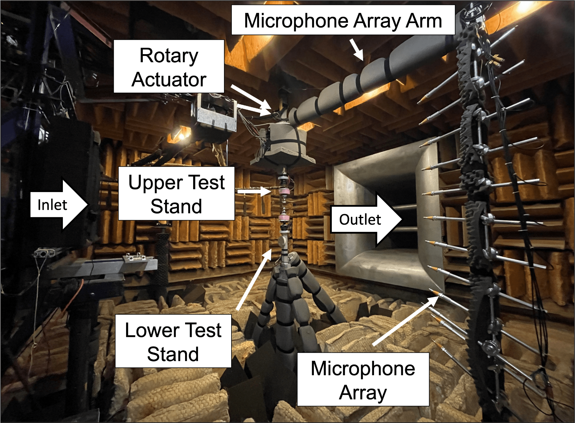
The multirotor test rig in a coaxial rotor configuration.

The multirotor test rig in a tandem rotor configuration.
A new, much larger and more capable, aeroacoustic wind tunnel is currently under construction as a part of the new Engineering Collaborative Research and Education (ECoRE) building. The figure below summarizes the planned capabilities.
 3D model of the new ECoRE anechoic wind tunnel.